PID Control with TurtleSim
Abstract
Move Turtle is a simple ROS python script that moves the turtle in ROS’s TurtleSim to specified coordinates (points). This project started as a class project for CSCI473 at the Colorado School of Mines (CSOM) and later evolved into a project I used to help me learn how close-loop systems can be created, the knowledge from which was used to help me with my work at CSOM’s Human Center Robotics (HCR) Lab.
Context
For some background, ROS stands for Robot Operating Systems. ROS is an open-source robotics middleware, usually paired with the Ubuntu operating system, that is used to better manage the software components/clusters of a robotic system. You can learn more about how to use ROS though ROS’s official wiki. The code you write in ROS is in either C++ or Python.
TurtleSim is a simple 2D robot simulator used as an introduction to ROS and ROS packages to new users of ROS. All TurtleSim does is open a simple 2D display with a turtle. That turtle acts as the “robot” and you can send messages to that “robot” to move and/or turn. Well moving, TurtleSim does generate some random error to simulate real world physics in a simple way.
Knowing what ROS and TurtleSim is, why was I using them? Well, back in Spring 2020 I was taking a class called “Human Centered Robotics” at the Colorado School of Mines as part of my undergraduate computer science class load. The class was taught by Dr. Hao Zhang. The class consisted of three projects and the first project consisted of setting up ROS, learning how to use ROS, and implement either as open-loop or close-loop algorithm that would make the turtle in TurtleSim draw an M. The original project description can be viewed HERE.
When I was taking the class, I completed this project by implementing an open-loop algorithm. This solution worked but it really sucked and draw an A that was “good enough” but no were near “great”. After submitting the project around the middle of February 2020, I forgot about until a year later in around February 2021.
Challenge
In February 2021, I got hired as a Research Assistant at the Human Centered Robotics (HCR) Lab in the Colorado School of Mines where I worked under Dr. Hao Zhang. The goal of the lab is to do research on “lifelong collaborative autonomy, with the goal of enabling robots to operate and adapt over long periods of time”. As of 9-1-2022 (September 1, 2022), the lab has moved from the Colorado School of Mines to the University of Massachusetts Amherst. But, when I worked there they were still located in Colorado.
At the HCR Lab, I was tasked to work on the Triton project. The Triton project consisted of multiple, dozens, of robots called Tritons. Tritons were triangular omni wheel ground robots that looked like this:
![]()
Along with the Tritons, eight IR Cameras from OptiTrack arranged within an “octagon order” a few feet above the ground. Using those cameras, Optitrack’s Motive software, a PC running Windows 10, and ROS; a 2 meter by 2 meter by 2 meter (x, y, z) space is created where the exact real world position of objects with motion capture markers can be determined.
My first task with the Triton project was to make scripts that made the Triton robot move to a specific real world position. At the time, I was not sure how to achieve this but I did remember the first project from CSCI473 where the idea of an close-loop system was introduced to me, so I started really researching close-loop systems and in turn, feedback systems.
Research
During my research, I discovered this great video by AerospaceControlsLab:
In this video, the idea of a PID system was shown and explained to me. A PID system is a close-loop, control loop, system that produces specific output(s) based on data from the real world. In basic terms, it’s a feedback system that adjusts it’s output based on the difference between the desired value and the measured value. This is the formula for a PID controller:
$$ u(t) = K_p e(t) + K_i \int e(t) dt + K_d \frac{de(t)}{dt} $$
- $u(t)$ is the control signal.
- $K_p$, $K_i$, $K_d$ are the proportional, integral, and derivative gains respectively.
- $e(t)$ is the error signal (the difference between the desired and actual output).
- $\int e(t) dt$ is the integral of the error over time.
- $\frac{de(t)}{dt}$ is the derivative of the error.
To learn more about it, check out AerospaceControlsLab’s video or this amazing wikipedia article which is formula is from.
After doing my research as well as getting some help from my smart friends and professors, I determined that using a Proportional Controller, P Controller, would be best to help the Triton reach a specific coordinate.
Sense the Triton is a ground robot, I only need to worry about the X and Y coordinates. Knowing this, I then had to determine what desired values and measured values to measure and process within the P Controller(s). In my research I found this amazing post on the ROS wiki called Go to Goal where they focused on the following errors:
- Distance Error: The difference in distance between the desired location (X, Y) and the current location (X, Y).
- Theta Error: The difference between the desired orientation and the current orientation.
Proposed Solution
Knowing all of this, the solution for getting the Triton to move to a specific real world coordinate is to use a Proportional Controller for the Triton’s distance error and theta error in respect to the goal coordinate and the Triton’s current coordinate. But before implementing this into a physical system, I wanted to test the idea in a simulation and, at the time, I thought using TurtleSim as the simulation was the best choice.
Testing In Simulation
With the theoretical solution outlined, I opted to initially validate it through simulation, rather than a real-world scenario. The real world is often cluttered with noise that could muddle the effectiveness of the solution and lead to dealing with irrelevant issues. Acknowledging this, I revisited my project from CSCI473 and adapted it as a testing ground for this theoretical solution.
After updating the old code from using ROS Melodic to use ROS Noetic and with some iterative refinement, I did get the proposed solution working in TurtleSim. Demonstrations of it’s functionality, with some cool goal coordinate paths, can be found at the end of this blog post. The code for all of this can be viewed HERE.
Conclusion
In summary, though this project, the TurtleSim turtle effectively navigates to set coordinates using the close-loop system, significantly outperforming my initial open-loop system from 2020. Successfully tested, I implemented this solution with the Triton robots. But real-world noise introduced unexpected issues requiring weeks of debugging and real world testing. After those weeks, I ultimately got the Triton to reach specific real-world coordinates by ultimately using the solution I tested in TurtleSim. Here is a demo of the Triton moving to specific real world coordinates using the method tested in TurtleSim:
In retrospect, I wish I used a simulation that better simulated real world physics. TurtleSim is great for learning but not great for testing real world robotics ideas. At the time, I thought it would be good enough for my simple use case but that was later proven not to be the case.
The primary objective of this blog post was to outline the creation of a closed-loop system enabling the turtle in TurtleSim, and subsequently the Triton robots, to precisely navigate to specified goal positions (X, Y). I believe this objective was achieved, but it might have garnered some interest in my work at the HCR Lab. Knowing this, I do have plans on making more blog posts about my work experience at the HCR Lab…
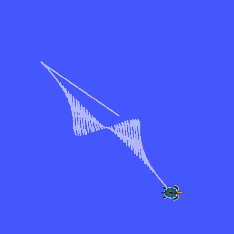
Moving Turtle (TurtleSim) Demos
This video contains the following demos:
- Cayley Nodal: A simple Cayley Nodal design
- Circles: A spider-web like design
- Inner Circles: A “circles inside of circles” design
- M: A very simple M design